Class Diagram
UML
How to Create UML Class Diagrams?
Written by:
How to Create a UML Class Diagram?
A class diagram is one of the most important tools in the Unified Modeling Language (UML), used to visualize classes and their relationships in an Object-Oriented Programming (OOP) system. A class diagram displays the system's classes, their attributes, methods, and relationships between them, such as inheritance and class associations. In this article, we will see examples of how to create a UML class diagram step by step.
Creating a UML Class Diagram Step by Step
Let's create a class diagram step by step. There are several online platforms that can help you create class diagrams or other types of diagrams. For this example, we will use the free website draw.io, one of the most popular tools for creating UML diagrams. If you prefer working with VS Code, the draw.io extension for VS Code allows you to create UML diagrams directly in your development environment.
1. Create a UML Diagram File
The following video will help you understand how to create a new file in draw.io and save it to your google drive account.
If you don't see diagrams.net in the "New" section of your Google Drive account, it means you haven't integrated this application with your Drive account yet. To integrate draw.io with your Drive account, follow these instructions:
- Click the
+ Newbutton, and a tab will open to choose the type of file you want to create. - Inside this tab, click the More button, which will open another tab with more options.
- In this new tab, click Connect more apps, which will open a small page where you can download and add more apps to your Drive account.
- On this page, type "draw.io" in the search bar, and when the application appears, click on it to see more details, and then click the Install button. Once installed, you can access it from your Google Drive account.
2. Identify the Necessary Classes
The second step in creating a UML class diagram is to identify the classes you will need for your project. A class is an abstract representation of an object with specific attributes and behaviors. For our example, we will model the classes needed for a book-selling application, essentially a library.
The main classes for creating this application are the following:
- Library: The Library class will be the main class of the application, containing all the books in our app.
- Book: The Book class represents a book and all its characteristics; this class is an aggregate class within the Library class.
- Person: This class will serve as an abstract class to represent common values for both the Salesperson and Customer classes.
- Salesperson: The Salesperson class will be a subclass of the Person class but with more specific attributes to represent a salesperson.
- Customer: The Customer class will also be a subclass of the Person class but with some additional features to better represent a customer.
3. Define Attributes and Methods
The third step is to define the attributes and methods of each class. Below, we will define these attributes for all the classes in our application.

As you can see in this example, we need to define each class along with its attributes and methods. The text strings at the top of the central line are attributes, and those at the bottom are methods. The basic structure of a class diagram is the following:
- To declare the attributes of our class, use the following symbols:
- (+) Public: Indicates that the attribute or method can be accessed from anywhere in the application.
- (-) Private: Indicates that the attribute or method can only be accessed from within the same class.
- (#) Protected: Indicates that the attribute or method can be accessed only from within the same class or from classes that inherit from it (child or subclass).
- Attributes are declared with the following syntax:
+ AttributeName: DataType
- Class methods are declared as follows:
+ MethodName(parameterName: ParameterType): ReturnType
This is the conventional structure for creating a class diagram, although it's important to note that there isn't an exact structure, as it depends on each project. Also, it's important to consider that the colors of the classes do not have a conventional structure; they are simply used to differentiate different types of classes, but you can use any colors you prefer or even not use colors at all.
4. Establish Relationships
The fourth and final step in creating a class diagram is to establish relationships between the classes, as shown in the following example:
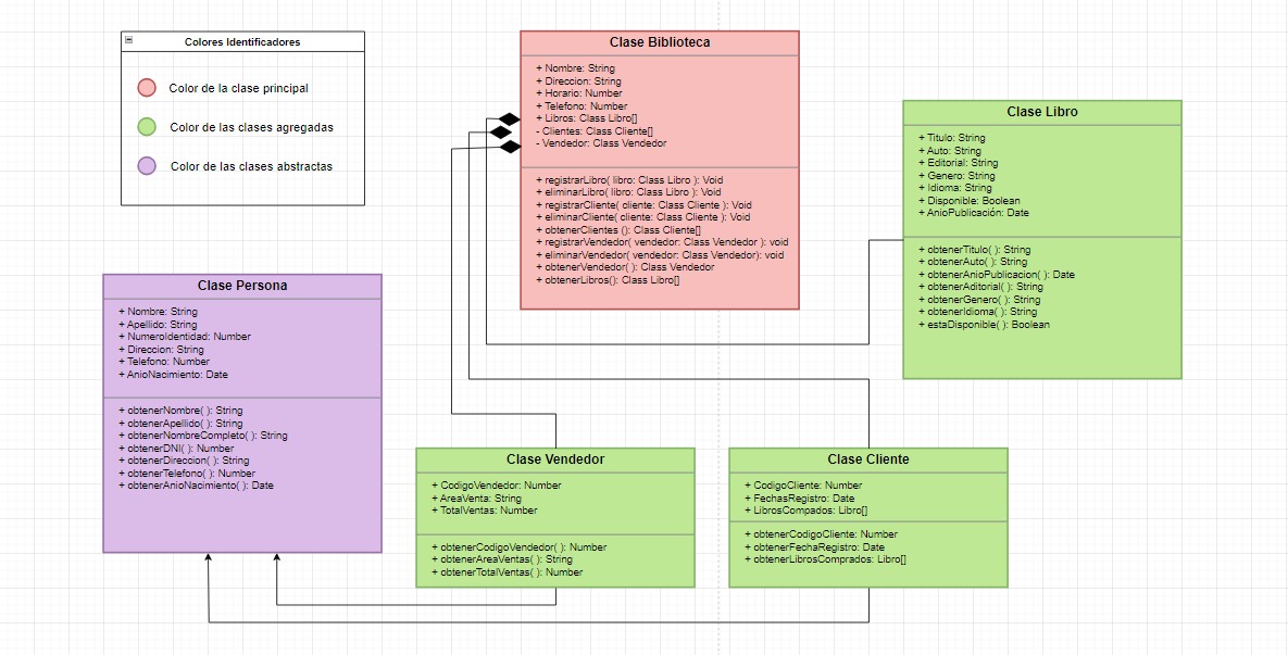
In this example, we relate the Person class, which is an abstract class, to its child or subclass classes, Salesperson and Customer, using a solid line with a triangle-shaped arrow. Then, we relate the main class, Library, to the other classes it contains: Book, Salesperson, and Customer, using a solid line with a rhombus-shaped arrow and a black background.
It's essential to note that when you design the UML diagram for your application, it won't be a static design. As you start generating code and want to add more attributes or classes that you didn't consider during the design phase, you can do so without any issues. Just keep in mind that the UML diagram design for your application should represent all attributes, methods, and interactions of your application as accurately as possible.
Applications for Creating UML Class Diagrams
There are several applications or websites that you can use to create UML class diagrams or other types of diagrams. Many of them have access to Google Drive for saving files. It's advisable to save your designs in cloud storage like Google Drive, GitHub, etc., for added security. Below are the three most commonly used applications for designing various types of diagrams:
- Draw.io: draw.io is a free and open-source tool that offers a wide range of templates, including UML class diagrams or other types like object diagrams or database diagrams. It allows you to save files in different locations such as Google Drive, GitHub, or your local storage.
- Visual Paradigm: visual paradigm is a comprehensive UML modeling application with an intuitive graphical interface for creating class diagrams and other UML diagrams.
- Lucidchart: lucidchart enables users to easily and quickly create UML diagrams. It's a good choice for both small and large teams and offers a wide variety of features.
Conclusion
UML class diagrams are an essential tool for modeling object-oriented systems. Creating them correctly and using the appropriate applications depending on the type of project allows us to visualize our system's structures more effectively, contributing to a more efficient and successful software development process. You can find more valuable information on the 4Geeks blog.